The millivolt output signal is the oldest signal, yet still has popular uses today. Sensors with millivolt output can be roughly separated into two categories; compensated and uncompensated. Compensated sensors are generally ones where the output has been trimmed with resistors to have a set zero and span tolerance, along with a specific sensitivity (commonly 5 or 10mV/V) over a specified temperature range such as 0-55°C. Uncompensated millivolt output is generally the raw output of the sensor that has not been adjusted or trimmed, and is usually stated with a typical output range, such as 100mV output, +/-25mV @ 10VDC excitation. With either choice, one common advantage of millivolt output is the response time to changes in pressure. The frequency response time of millivolt output sensors is fast because there are no circuits to slow down the signal changes.
Choosing compensated vs uncompensated depends on the needs of the application. If the application includes a signal conditioner that simply amplifies the sensor output, compensated is usually the better choice because the sensor is already set to meet published performance over a specified temperature range. If the application is one where the equipment will be characterized and compensated/error corrected as a whole using a signal conditioner that can set zero, span, and temperature compensation, an uncompensated output is a good choice because it maximizes that output available for adjustments and error correction.
In physical terms, one of the primary advantages of millivolt output sensors is size and packaging flexibility. Because there are no ICs and other large electronic chips to fit inside the sensor housing, millivolt sensors are more flexible in design to fit into embedded systems and customized equipment.
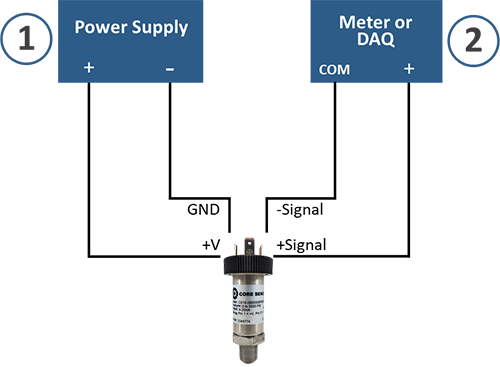
Millivolt Wiring Schematic
How To Guide
For this how to guide, we have three components; power supply (labeled as 1 in the schematic), Core Sensors pressure transducer, and a meter or other DAQ system (labeled as 2 in the schematic).
1) Power Supply – Connect the positive (+) terminal of the power supply to the +V pin or wire of the transducer. Connect the negative (-) terminal of the power supply to the Ground (GND) pin or wire of the transducer.
2) Meter or other data acquisition (DAQ) – Connect the COM terminal of the meter of DAQ to the -Signal pin or wire of the transducer. Connect the Volts input terminal of the meter or DAQ to the +Signal pin or wire of the transducer.
This will complete the 4-wire circuit.
* In certain circumstances, there may be an additional pin or wire used as a case ground. This connection is not critical to the output signal but may be critical to maintain listed certifications of the transducer. Please refer to the Core Sensors wiring guides to verify wiring prior to installation.
Advantages
- Noise resistance due to lack of ICs.
- Fast response time to changes in pressure.
- Perfectly ratiometric, so any power supply will work (up to the max VDC)
- Flexible design possibilities for embedded systems
Disadvantages
- Requires 4-wire connection
- Possible low signal to noise ratio in applications where EMI/RFI is present
- Limitations on signal transmission distances
- Often requires external/additional signal conditioner
Common Applications
High Performance Liquid Chromatography (HPLC) – mV sensors are common in HPLC because often the system and pumps are calibrated as a whole and/or the system already has an on-board signal conditioner with trimming features to re-calibrate the equipment when needed. Also, mV sensors can be made as custom embedded units more easily, resulting in lower “dead volume”, which is important in HPLC applications to reduce cross-sample contamination.
Mass Flow Controllers (MFC) – Use of mV sensors in MFCs is common for similar reasons as the HPLC, with the additional need for fast response time. The fast response time of mV sensors in the MFC is vital to fine tune the amount of product that is allowed to flow into the process.
Scales and weighing equipment/hydraulic press and forming – mV sensors are used in hydraulic weighing and machine press applications to replace load cells. The mV output of the sensors is similar to the mV output of many load cells, allowing OEMs to minimize system redesign when upgrading from a load cell to a pressure sensor.
Higher ambient temperature applications – In applications such as super-heated steam, downhole drilling and MWD, or applications measuring pressure in a engine compartment of a moving or stationary engine, temperatures can climb to a range that is not compatible with ICs and ASICs. Because of the lack of ICs, mV units can generally be installed in locations that are simply too hot for amplified sensors, and the signal is transmitted to a remote signal conditioner.
Heating, Ventilation, Air Conditioning, and Refrigeration (HVAC/R) – There are numerous applications in HVAC/R systems where pressure is measured. Often, there is a need for two separate sensors to be used to measure pressure in two spots to provide operators with the differential pressure reading. These PLCs are designed to accept two mV signals and report the differential pressure. The CS10 industrial pressure transducer with a millivolt output signal would be an ideal solution to handle this type of application.