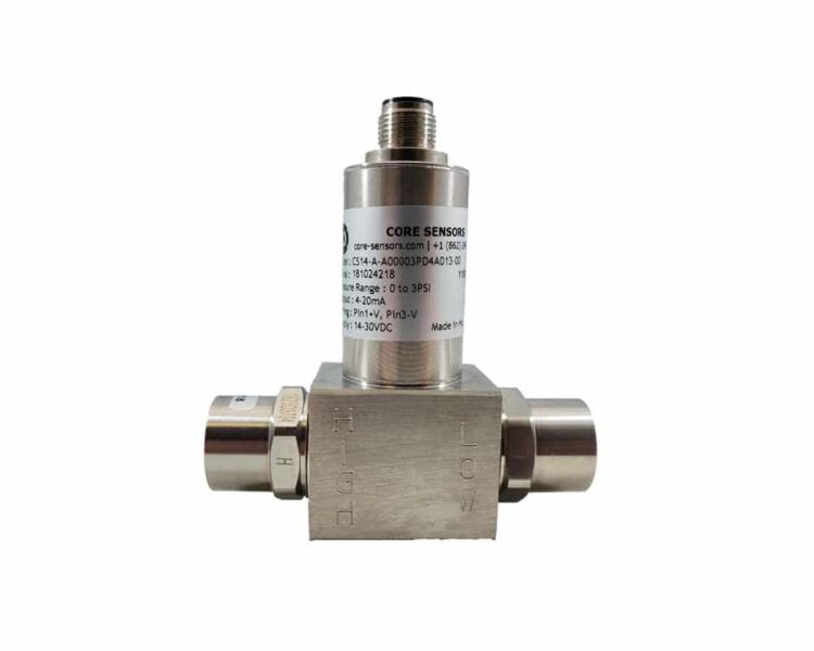
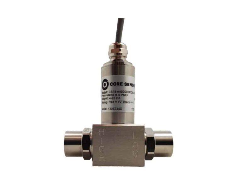
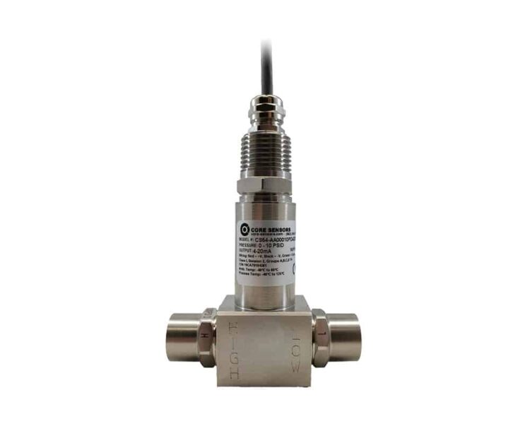
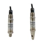
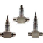
Core Sensors CS84 Series

  • Core Sensors

Product Features

  • Intrinsically safe differential pressure transducer
  • Differential pressure up to 50 PSI
  • Maximum line pressure of 500 PSI
  • Bi-directional pressure ranges
  • Accuracy of ≤±0.25% BFSL
  • Stability of ≤±0.25% of FS
  • Pressure cycles of 4 million
  • CSA

Applications

  • Compliant


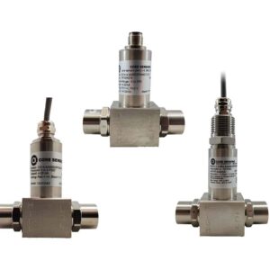
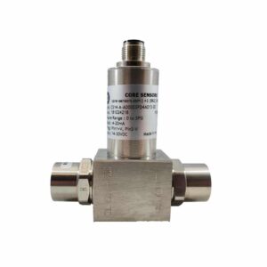
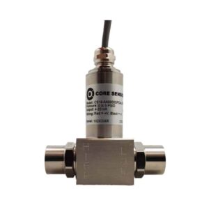
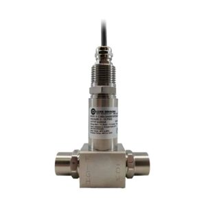
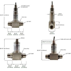
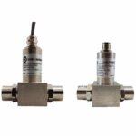
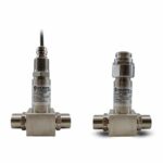
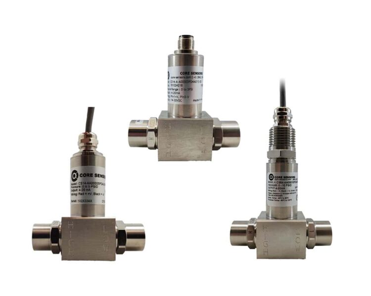
The CS84 intrinsically safe differential pressure transducer series from Core Sensors is a high-strength sensor designed for differential pressure measurements of liquids and gases in Class I, Division 1 intrinsically safe environments. The CS84 all welded stainless steel construction provides a minimum IP65 rating. Excellent stability is achieved with the 316L SS oil filled sensor element over a wide operating temperature range of -20 to +80°C (Electrical Connection “F”, DIN 43650-A) while offering corrosion resistance against various liquids and gases. Differential pressure ranges up to 50 PSI are available with 1/4″ MNPT or FNPT process connections. A wide range of configurable options make the CS84 a versatile pressure transducer that can be designed to operate in some of the harshest conditions.

The CS84 is the ideal solution for differential pressure measurement in hazardous applications such as filter condition monitoring, sealed tank level measurement, and flow measurement across an orifice.
The CS84 features a fully welded design without any internal O-rings or seals, allowing for wet/wet, wet/dry, or dry/dry applications. Differential pressures are available as low as 1 PSID up to 50 PSID in both uni-directional and bi-directional. Multiple electrical connections and outputs are available

  • Intrinsically safe differential pressure transducer
  • Differential pressure up to 50 PSI
  • Maximum line pressure of 500 PSI **
  • Bi-directional pressure ranges available
  • Accuracy of ≤±0.25% BFSL (≤±0.5% BFSL 2 PSI & below) *
  • Stability of ≤±0.25% of FS (1 year)
  • Pressure cycles of 4 million
  • Overpressure of 2X or 500 PSI (whichever is less, configured differential pressure) ***
  • Burst pressure of 3x (configured differential pressure) ***
  • Maximum differential pressure
  • Temperature range −40°C to +80°C (−20°C to +80°C for Electrical Connection “F”, DIN 43650-A)
  • Media temperature range −40°C to +125°C (−40°C to +105°C for Electrical Connection “F”, DIN 43650-A)
  • Electrical output options of 4-20mA, 1-5V, 1-6V, 0.5-4.5V ratiometric or 0.5-2.5V non-ratiometric
  • 316L SS diaphragm / oil filled sensor element
  • All welded stainless steel construction for a minimum IP65 rating ****
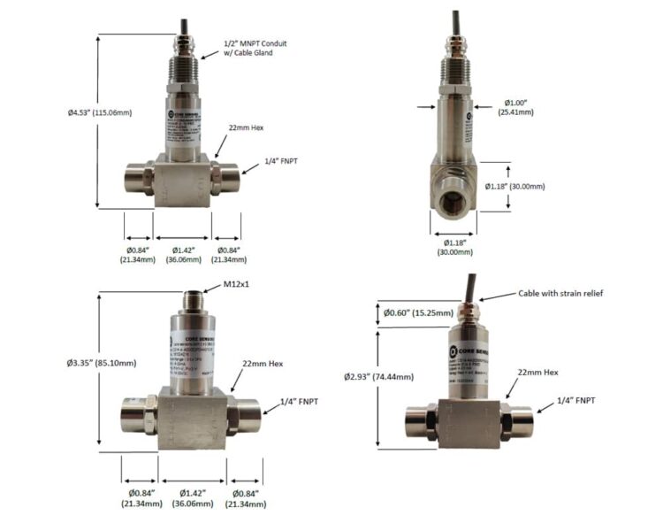
  • 1/4” NPT or FNPT process connections

* Accuracy includes non-linearity, hysteresis and non-repeatability
** Max line pressure is the highest common mode pressure that can be applied to the sensor without damage
*** Overpressure and burst pressure are the maximum differential pressure that can be applied to the high or low side before damage to the sensor will occur
**** IP Rating applies when the electrical connector is attached with the appropriate ingress protection and is dependent on the electrical termination selected. Contact us for more information.

Approvals for the Core CS84 series include:

  • CSA Class I, Division 1 Groups C,D T4
  • Class I, Zone 0 AEx ia IIB T4 Ga (Ex ia IIB T4 Ga)
  • ABS (American Bureau of Shipping)
  • CE

Note: Must use an approved barrier to maintain listed certifications. See page 4 of the datasheet for entity parameters.

Typical applications for the CS84 intrinsically safe differential pressure transducer include:

  • Filtration
  • External fuel tank level measurement
  • Compression systems


Performance, Thermal, Environmental & Physical Specifications Table

AttributeValue
Accuracy at 25°C *≤±0.25% BFSL
≤±0.5% BFSL (2 PSI & below)
Stability (1 Year)≤±0.25% of FS
Pressure Cycles4 million
Maximum Line Pressure **500 PSI
Overpressure ***2x or 500 PSI (whichever is less, configured differential pressure)
Burst Pressure ***3x configured differential pressure
Operating Temperature-40°C to +80°C
-20°C to +80°C for DIN 43650-A
Media Temperature-40°C to +125°C
-40°C to +105°C for DIN 43650-A
Compensated Temperature0°C to +55°C
Storage Temperature-40°C to +125°C
TC Zero≤±1% of FS
≤±2% of FS (2 PSI & below)
TC Span≤±1% of FS
≤±2% of FS (2 PSI & below)
EMI / RFI ProtectionYes
IP Rating **IP65 minimum
Vibration10g, 20 to 2000Hz
Shock100g, 11msec, 1/2 sine

Electrical Specifications (Current)

AttributeValue
Outputs4 to 20mA
Excitation10 to 28VDC
Current Consumption20mA (typical)
Output Load0 to 800Ω at 10 to 28VDC
Frequency Response~250Hz (minimum)
Zero Offset (of FS)≤±0.5% (typical)
±1% maximum
Span Tolerance (of FS)≤±0.5% (typical)
±1% maximum

Electrical Specifications (Voltage)

AttributeValue
Outputs1 to 5V
1 to 6V
Excitation10 to 28VDC
Current Consumption<10mA
Output Load5kΩ (minimum)
Frequency Response~1kHz (minimum)
Zero Offset (of FS)≤±0.5% (typical)
±1% maximum
Span Tolerance (of FS)≤±0.5% (typical)
±1% maximum

Electrical Specifications (Ratiometric Voltage)

AttributeValue
Outputs0.5 to 4.5V ratiometric
Excitation5VDC ±0.5V
Current Consumption<10mA
Output Load5kΩ (minimum)
Frequency Response~1kHz (minimum)
Zero Offset (of FS)≤±0.5% (typical)
±1% maximum
Span Tolerance (of FS)≤±0.5% (typical)
±1% maximum

Electrical Specifications (Low Power Voltage)

AttributeValue
Outputs0.5 to 2.5V non-ratiometric
Excitation3 to 5VDC unregulated
Current Consumption≤3mA
Output Load5kΩ (minimum)
Frequency Response~1kHz (minimum)
Zero Offset (of FS)≤±0.5% (typical)
±1% maximum
Span Tolerance (of FS)≤±0.5% (typical)
±1% maximum


ImageText
danger iconCaution must be taken when installing and operating the CS80, CS81, CS82 and CS84 in known Class I, Division 1, Groups A,B,C,D hazardous locations. Any misuse or improper installation may impair the equipment’s intended use and/or protection ratings. Thoroughly read and understand the operating instructions prior to installation. Call us on +44 (0) 1342 330 470 if you are unsure about any of the precautions or instructions or require other details on this or any other core sensor components.


Core Sensors design and manufacture high-quality sensors for measuring pressure and temperature properties for industrial and hazardous applications worldwide. Core offers solutions for industrial, submersible, differential and hazardous applications in both standard and custom packaging. In-house design and manufacturing capabilities along with strategic manufacturing partners allow Core to create solutions to some of the most complex sensor requirements. Please visit https://core-sensors.com for more information.

Clear
Quantity
Calculators and Convertors

Work out what you need for your project. Go to calculators and convertors

Contact us if you need your items quicker or need more than in stock.

Specifications

Product Type

,

Process Connection

,

Wetted Material

Pressure Range

Pressure Unit

,

Pressure Type

,

Output

, , ,

Electrical

, , , ,

Options

Temperature Range (°C)

Accuracy

,

Lead Length

, , ,

Series / Model

Core Sensors CS84 Series Ordering Info

Below is the model number configuration for the CS84 series from Core Sensors.

Ordering example: CS84-AA00010PD4A000-00
CS84XXXXXXXXXXXXXXXX

Series / Model (CS84)

CS84
CS84

Process Connection (X)

2
1/4” Male NPT
A
1/4” Female NPT

Wetted Material (X)

A
316L SS

Pressure Range (XXXXX)

Insert 5digit pressure code, max 50 PSI
i.e. 00050 = 50 PSID

Pressure Unit (X)

P
PSI
W
Inches of H2O

Pressure Type (X)

B
Bidirectional
D
Differential

Output (X)

1
1 to 5V
2
0.5 to 4.5V ratiometric
4
4 to 20mA
8
0.5 to 2.5V non-ratiometric

Electrical (X)

A
M12x1
D
Mini-DIN, Form C
F
DIN 43650, Form A
L
Cable
Z
1/2″ MNPT conduit with strain relief

Options (XXX)

000
No special options

Lead Length (XX)

00
No cable
01
1m
02
2m
03
3m

Core Sensors CS84 Series Resources

Product Datasheet

Supporting Product Information

Supporting Manufacturer Information

  • Core Sensors

Core Sensors CS84 Series

Please be advised that due to the ongoing supply issues with raw materials affecting the global electronics industry, as well as an increase in orders received by our manufacturing partners, a large number of products are facing increased lead times in recent months. For the latest lead time and stock availability, please contact one of our engineers who will be happy to discuss lead times further and the potential for alternative parts.